GREAT WESTERN NETWORK HEAD END
|
|
< - - Click for video tour |
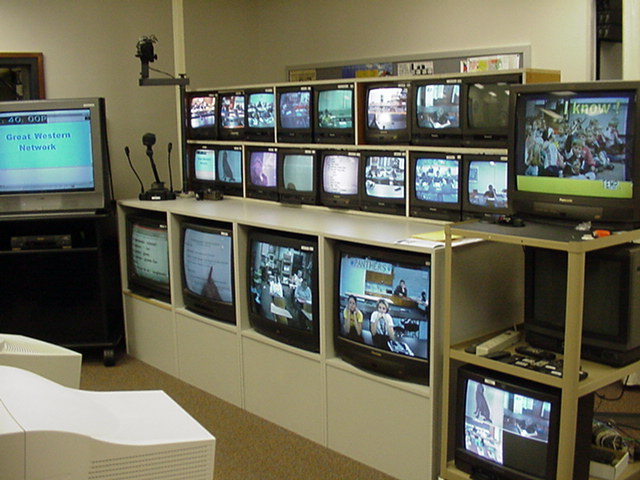
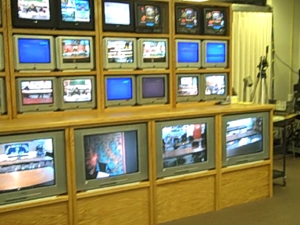
Monitors for some of the sites on the network
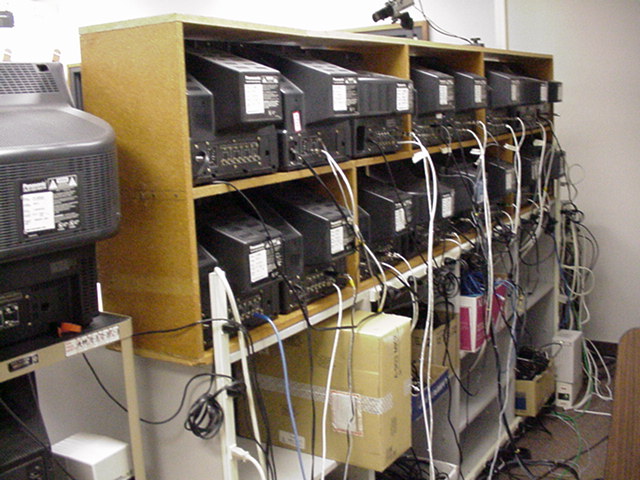
Not as pretty from the back view
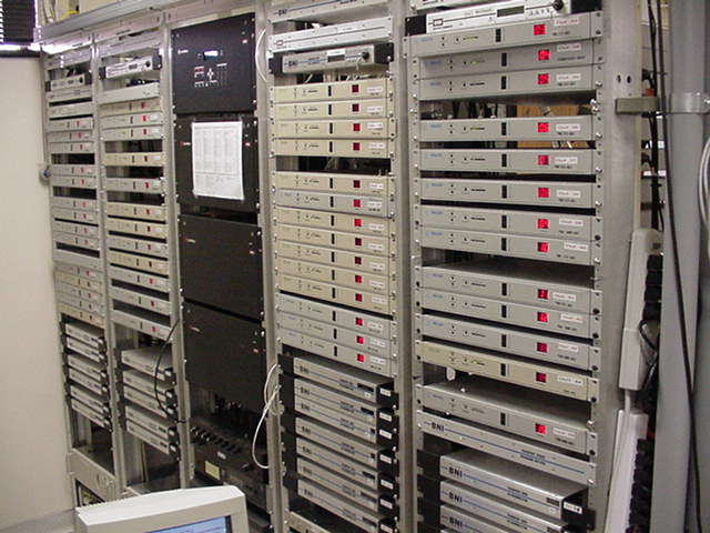
BNI (Broadband Networks Inc.) and Philips Analog gear front view with Autopatch Enclosures in the middle
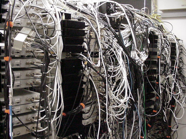
Back view of analog gear
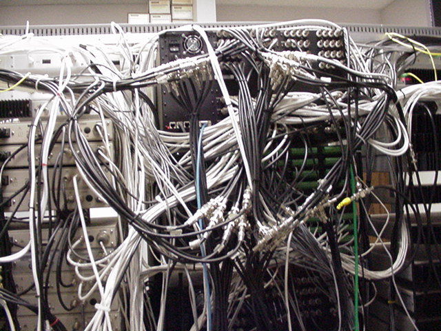
Believe it or not, there is an Autopatch 64 x 128 router behind these wires
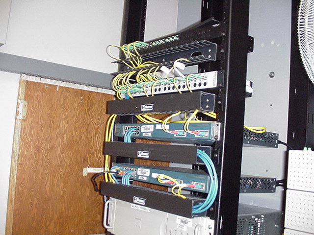
State Network gear - Cisco Gigabit Ethernet switches and Fiberdyne wdm devices.
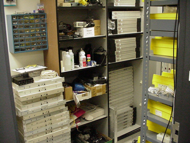
Spare Philips and BNI gear
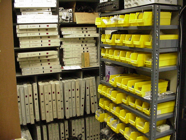
Spare mods, demods, and misc. connectors
Technical Information about our network:
For our FM analog locations, we use a combination of Philips and BNI (http://www.bnisolutions.com) Transmission Equipment Rack located at the Hub Site at Washburn High School. All schools also have digital capabilities for transmission using polycom h.323 systems.
Audio / Video equipment is switched using a pair of 256 x 256 Audio / Video AMX-Autopatch Epica matrix router.
Each of the sites in the Great Western Network have the following equipment located near their ITV classroom:
At least 1 transmitter (the device that generates the fiber optic light stream) (1300 nm window)
At least 1 transceiver (the device that receives the light stream from the previous site)
1 modulator (the device that takes the video and audio signal generated by the classroom equipment (cameras, microphones, etc.) and place it into the light stream.
3 demodulators (the device that takes the previously generated signals and converts it back to video and audio and then back into the classroom). One demodulator for each classroom monitor.
A gigabit ethernet switch to carry the data traffic on the 1550 window of the fiber. The North Dakota ITD (Information Technology Division) manages and maintains this portion of the network and utilizes Extreme Network switches at each school location.
The above equipment allows A/V signals to travel up to approximately 35 miles before the signal needs to be repeated.
The equipment behind the teachers console from top to bottom consists of the playback/record switch for the VCR, the VCR, Incoming Amplifier and on the bottom, the Outgoing Mixer. In this photo, a Picture-In-Picture unit is installed to the left of the VCR on the top shelf.